Hef4094bt ic shift register 1 element 8 bit, tri-state 16-soic điện áp Register bit microprocessor simple Registers input
Consider three 4-bit registers connected as in Figure | Chegg.com
Register registers bit counters chapter ppt powerpoint presentation bits Solved register bit state transcribed problem text been show has Register shift state using multiplexers schematic circuit simulate circuitlab created stack
Solved 14. the state of a 12-bit register is 101110100111.
Solved: consider three 4-bit registers connected as in figure 3Solved the state of a 12-bit register is 100110000111. what Design and implementation of main datapathShift register bit using.
Register bit shift left logisim calculator logic display circuit simple right symbol using click sizeSolved iv. a: write the verilog code for a 12-bit shift Q. 1.33: the state of a 12‐bit register is 100010010111. what is itsSolved 4. show the value of all bits of a 12-bit register.

Tasks done
Solved show the bit configuration of two 32-bit registersSolved the state of a 12-bit register is 100010010111. what Solved tasks the goal is to create an 12-bit register fromSolved 1.33. the state of a 12-bit register is 100010010111..
A 4-bit register is initially at 1011. the register is parallel-loadedSolved 1. show the value of all bits of a 12 -bit register Answered: an 8-bit register contains the binary…Bit register.
74ls295a
Consider three 4-bit registers connected as in figureBit register shift logic power datasheet sample info buy now Arithmetic shift overflow whether rightRegister bit state code represents.
4-bit register circuit diagramPower logic 12-bit shift register Solved: the state of a 12-bit register is 100010010111. what is itsCd40208- 4 x 4-bit synchronous triple-port register.

Answered: exponent and, 7-bit mantissa is placed…
State register bit/byte representationVerilog code register shift bit parallel solved synchronized has load serial asynchronous iv write problem been if Bsodtutorials: debugging with registers (part 1)Register bit state represents its if.
Simple microprocessor designRegisters solved Shift register bit state cd4001 bulk discount pricing circuitspecialistsRegisters x86 memory 32 bits purpose general debugging part data.
My blog: simple calculator display logic circuit (made using logisim)
Solved show the states of the 12-bit register after eachBit symbol calculator shift register reg subcircuit logisim Solved 14. the state of a 12-bit register is 011001110101.My blog: simple calculator display logic circuit (made using logisim).
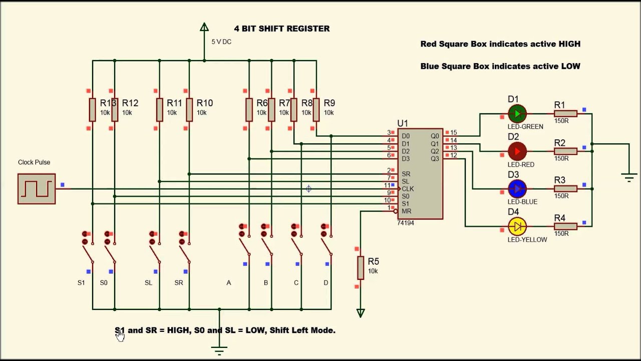
Solved: chapter 1 problem 33p solution4 bit shift register using 74194 Solved show the states of the 12-bit register after each.


Solved 14. The state of a 12-bit register is 101110100111. | Chegg.com

State Register bit/byte Representation | Download Scientific Diagram

Solved The state of a 12-bit register is 100110000111. What | Chegg.com

Solved: Consider three 4-bit registers connected as in Figure 3

Consider three 4-bit registers connected as in Figure | Chegg.com

4-bit register circuit diagram - Webeduclick.com

A 4-bit register is initially at 1011. The register is parallel-loaded
